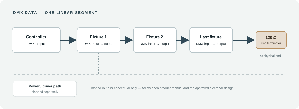
For building facades, landscape installations, hotels and commercial interiors, these decisions affect whether multiple luminaires change color together, respond independently and operate consistently over long cable runs.
Safety note: This is a system-planning and commissioning guide, not a substitute for the manuals of the actual controller, driver, decoder or luminaire. All mains-voltage work, protective earthing, weatherproof electrical connections and other regulated electrical installation tasks must be handled by appropriately qualified personnel in accordance with applicable local codes. Isolate power before making or changing wiring connections.
1. What is DMX512, and why is it used for architectural lighting?
DMX512 is defined by ANSI E1.11, the entertainment-lighting data transmission standard maintained through ESTA. The current published edition is ANSI E1.11-2024. Although DMX originated in entertainment lighting, it is also widely used in architectural systems where many fixtures need coordinated brightness, color or programmed scenes.
A DMX channel carries an 8-bit control value, usually described as 0–255. A DMX universe provides up to 512 control slots (channels). This is the amount of control data available within a universe, not the number of physical fixtures permitted on one cable segment.
A simple white-light dimming device might use one channel. An RGB luminaire might use three. A straightforward RGBW profile can use four—one each for red, green, blue and white. A fixture with master dimming, strobe functions or pixel control may require more. The fixture's published DMX personality or channel chart determines the real channel count.
DMX is particularly useful when an installation needs dynamic RGB/RGBW effects, group control or coordinated scenes across a facade. A fixed white-light application with simple dimming may be better served by another compatible control approach. Choose the protocol around the project's requirements, not because one protocol is universally superior.
2. Know the system: controller, signal network, luminaire and power
There are two common architectures. The correct one depends on the product you are actually buying.
A. Luminaire with built-in DMX-compatible electronics
Lighting controller → DMX data line → DMX-capable wall washer 1 → wall washer 2 → ... → last luminaire / termination
Separately, an appropriately rated supply distributes power according to each luminaire's specified input. A built-in DMX receiver may not eliminate the need for a separate driver or power system—check the luminaire specification.
B. Low-voltage RGBW luminaire or LED strip controlled through a DMX decoder
Lighting controller → DMX data line → DMX decoder → correctly rated RGBW LED output
The decoder receives DMX data and controls the LED channels using the electrical output type required by the load. Its separate power input must be matched to the LEDs and decoder. A generic PWM decoder must not be assumed to work with every constant-current architectural fixture.
For either architecture, confirm the following before procurement:
| Component | Check before approval |
|---|---|
| DMX controller / gateway | Number of universes, scene requirements, output connectors and addressing interface |
| Luminaire / decoder | Actual DMX personality, channel chart, address-setting method, electrical input and connector pinout |
| Power supply / driver | Voltage, current, load, efficiency, environmental rating and any required control interface |
| Data cable | Appropriate DMX-rated shielded twisted pair, cable routing and installation environment |
| Splitter / repeater | Use when the topology requires multiple branches, more receiver load or regeneration |
| Last device | Manufacturer-approved internal or external DMX line termination |
Do not confuse DMX data conductors with DC output conductors or mains supply conductors. They serve different purposes and must not be connected by matching colors or assumptions.
3. DMX wiring topology: daisy chain, not a passive star
A conventional DMX data segment follows a daisy-chain topology:
CONTROLLER → FIXTURE 1 → FIXTURE 2 → FIXTURE 3 → TERMINATOR
The controller's data output reaches the first receiver, then continues from that receiver to the next. Avoid a passive Y-split or uncontrolled star wiring: branches can produce reflections and intermittent errors.
Where a project needs multiple building wings, facade elevations or landscape zones, use a properly designed DMX splitter, preferably with optically isolated outputs where appropriate. Each output becomes a separately managed segment with its own end-of-line termination.
Electrical loading and channel capacity are separate limitations. Classic RS-485-based DMX distribution is often planned around 32 unit loads per segment. One modern receiver may draw less than one unit load, so the actual permitted device count depends on published receiver loading, cable, controller and splitter specifications. Never interpret the 512 channels in a universe as permission to connect 512 luminaires in one physical line.
Cable-run limits also depend on equipment, cable quality and installation conditions. Long exterior runs should be engineered and tested rather than relying on a universal distance claim.
4. DMX connectors and signal polarity
ANSI DMX512-A uses a 5-pin XLR connector as its standard connector arrangement. In its primary data link, the commonly used signal assignment is:
| Pin | Signal |
|---|---|
| 1 | Data-link common / shield |
| 2 | Data 1− |
| 3 | Data 1+ |
| 4–5 | Reserved / optional secondary data link according to device implementation |
Real-world architectural equipment may use 3-pin connectors, terminal blocks or dedicated waterproof connectors. These are not interchangeable by appearance. Always compare the manuals and marked terminals at both ends; do not guess from wire colors, and do not assume every RJ45 or waterproof connector uses the same pinout.
Use installation-suitable data cable and the manufacturer's wiring instructions. Keep sensitive signal cabling appropriately separated from high-current or mains circuits as required by the installation specification and local electrical rules.
5. Why is a 120-ohm DMX terminator important?
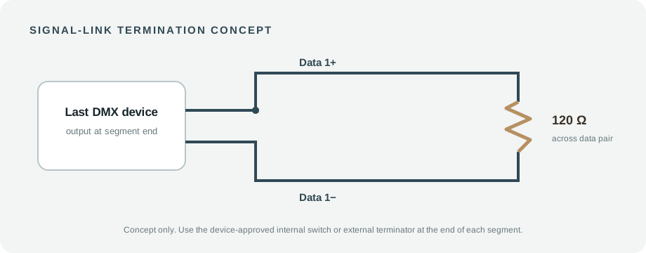
DMX uses a balanced differential data link. An improperly terminated run may suffer signal reflections, especially over long distances or with more receivers. The conventional solution is a 120 Ω terminator between Data 1+ and Data 1− at the physical end of the DMX line.
Termination belongs at the actual end of each segment, not arbitrarily at every luminaire. Some devices have built-in or selectable termination; others use a plug-in terminator or installation-specific component. Follow the product documentation. If a splitter creates several independent outputs, treat each branch according to the splitter and receiver manuals.
Symptoms of topology or termination problems can include flicker, unexpected colors, response delay or failures that occur only when the entire line is connected. These symptoms can also have other causes, so termination should be checked as part of a wider diagnosis.
6. Understanding DMX addresses and channel modes
Every independently controlled DMX fixture needs a starting address and an appropriate DMX personality / operating mode. The fixture reads a block of channels beginning at that address. Two fixtures can intentionally share an address to mirror each other, but accidental overlap can produce confusing behavior.
Example: a simple four-channel RGBW profile
For this illustrative mode only:
| Channel offset | Function |
|---|---|
| +0 | Red |
| +1 | Green |
| +2 | Blue |
| +3 | White |
A fixture starting at address 1 uses slots 1–4. If the next independently controlled fixture uses the same four-channel mode, give it address 5; the next uses address 9. A four-channel RGBW fixture starting at 45 would occupy channels 45–48.
| Fixture | Starting address | Occupied slots |
|---|---|---|
| RGBW wall washer A | 001 | 001–004 |
| RGBW wall washer B | 005 | 005–008 |
| RGBW wall washer C | 009 | 009–012 |
| RGBW wall washer D | 013 | 013–016 |
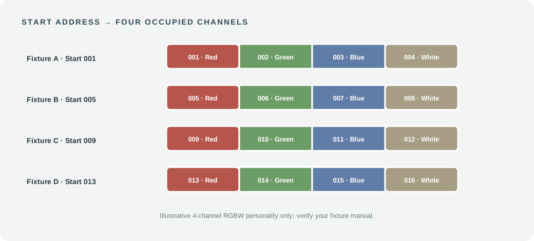
Important: This is not a universal RGBW address map. Some fixtures need five channels (master dimmer plus RGBW), six or more channels (strobe, effects, segments), or entirely different mappings. Verify the manufacturer's DMX channel chart before assigning addresses or programming a controller.
How many RGBW luminaires fit in one universe?
Purely mathematically, 512 ÷ 4 = 128 independent four-channel address blocks. However, 128 is not a recommended physical daisy-chain count. Power distribution, RS-485 receiver loading, cable length, electrical zoning and installation reliability can require several splitter branches. Each branch can still use the same universe and its 512 available channel values.
For a project with 20 independent four-channel luminaires, the channel budget is 20 × 4 = 80 slots. If all 20 are deliberately grouped at the same starting address, they can behave as one group, but independent scene control is lost for those units.
7. A practical commissioning sequence for LED wall washers
The safest, most repeatable process is to separate design approval, physical installation, controller configuration and functional verification.
Step 1 — Confirm the equipment list. Collect the controller, gateway, splitter, driver, decoder and luminaire model numbers. Request the relevant manuals, DMX channel charts, data-pin assignments, voltage/current requirements and environmental ratings.
Step 2 — Draw two networks. Create one diagram for DMX data routing and a separate one for electrical power distribution. Mark every fixture, junction, splitter, segment endpoint and the locations of suitable weatherproof enclosures.
Step 3 — Prepare a channel schedule. Record each fixture ID, position, operating mode, starting address, occupied slots, universe and control group. Check for accidental overlap before site work begins.
Step 4 — Install and inspect in accordance with the approved electrical design. Qualified installers should follow local codes, manufacturer instructions, supply protection requirements and any exterior ingress-protection details. Keep the equipment de-energized when making or modifying connections.
Step 5 — Build a small test segment. Before commissioning an entire facade, verify the controller and one or two fixtures with the intended cable and the correctly specified power system. Confirm that addresses, personality modes, R/G/B/W responses and fixture behavior match the documentation.
Step 6 — Extend and terminate each run. Add receivers in the planned order, check connector polarity, receiver load and data-line termination, then verify splitter branches individually.
Step 7 — Test individual and grouped scenes. Verify red, green, blue and white output separately, then dimming, combined colors, scene transitions and blackout/recovery behavior. A fixture profile may implement additional functions that require separate tests.
Step 8 — Document handover. Save the final controller configuration, cable drawings, address schedule, device manuals, tested scenes and troubleshooting notes for the owner and maintenance team.
8. Troubleshooting: what to inspect when the system misbehaves
| Symptom | Potential cause | First verification |
|---|---|---|
| One wall washer does not respond | Wrong address, incorrect mode, no data or no power | Verify its supply, status indicators, address and channel profile |
| All fixtures on one branch fail | Controller output, splitter output or trunk-cable issue | Test an isolated known-good segment and check the intended output |
| Colors do not match controller commands | Wrong fixture personality or channel order | Compare controller patch with the product's exact DMX chart |
| Flicker or random scene changes | Cable fault, polarity problem, reflections, interference or overloaded segment | Inspect physical topology, connector assignments, cable and end termination |
| Some fixtures mirror each other unexpectedly | Shared or overlapping starting addresses | Review address schedule and grouping intention |
| System works near controller but not farther away | Cable quality, long run, receiver loading or branch design | Check cable specification, segment load and whether an isolated splitter is required |
| Light output is weak or unstable | Power-supply sizing or voltage drop; not necessarily DMX | Verify electrical supply and load measurements through a qualified technician |
Troubleshoot systematically. A DMX problem and a power-distribution problem can look similar at the fixture, but they require very different solutions.
9. Power planning: DMX does not supply fixture power
A DMX controller communicates instructions; it does not automatically provide the correct electrical supply for every wall washer. For a low-voltage system, confirm the luminaire's rated input voltage, driver behavior, cable length, total watts, current, environmental conditions and inrush or other manufacturer-specific requirements.
For example, a hypothetical 24 V, 120 W LED load draws 120 ÷ 24 = 5 A at its rated operating point. A supply with adequate manufacturer-recommended headroom might be required, but a single fixed oversizing percentage is not suitable for every driver and project. Long runs may also need voltage-drop calculations or separate power injection points. This example is not a FANXING product specification.
For AC-input architectural luminaires, follow their own approved driver, protection, isolation and wiring instructions rather than using the low-voltage decoder example.
10. DMX512 vs DALI vs 0–10V: which is appropriate?
| Control method | Typical strength | Project consideration |
|---|---|---|
| DMX512 | Dynamic RGB/RGBW scenes, coordinated color effects | Addressing, universe capacity and robust data topology need planning |
| DALI | Digital control and management of compatible architectural fixtures | Requires the correct DALI devices, application controller and bus architecture |
| 0–10V | Relatively simple analog dimming of compatible luminaires | Control behavior, wiring and interoperability depend on the exact devices |
No protocol is automatically best for every job. A facade with programmed RGBW effects may fit DMX; a commercial building with widespread individually addressable general lighting may have different control requirements. System selection should come before choosing the final driver and luminaire control option.
11. What should a project buyer send to the manufacturer?
A precise inquiry saves engineering time and reduces the risk of supplying a compatible luminaire with an incompatible controller.
Include, when available:
- Architectural elevation or lighting layout indicating wall-washer positions.
- Required colors (RGB, RGBW or tunable white), beam angles and control scenes.
- Fixture model or desired dimensions, quantity, operating voltage and applicable ingress-protection requirements.
- Controller or gateway make/model, DMX universe allocation and preferred connector type.
- Intended independent control groups and approximate data-cable run lengths.
- Installation country, supply characteristics and locally required compliance documents.
- Desired fixture channel profile, if the control design has already been prepared.
- Relevant schedule for samples, approval, production and shipping.
Request a documented compatibility review and, for more complex systems, a sample-based functional test before bulk supply. Where an independent lighting designer or electrical engineer is responsible for the overall system design, coordinate the final configuration with that professional.
Frequently asked questions
Does each DMX wall washer need a different address?
Only when separate control is required. Fixtures intentionally assigned the same starting address and compatible operating mode can respond together. Fixtures that must behave independently need non-overlapping address ranges within their assigned universe.
Can I connect 512 fixtures to one DMX line?
No. 512 refers to channel slots per universe, not the physical receiver capacity of a data segment. Segment loading, termination, cable, controller hardware and splitters determine viable physical distribution.
Is a DMX decoder always required for RGBW wall washers?
No. Some luminaires have built-in DMX-compatible receivers or drivers; others need a separate decoder. Use the actual luminaire and driver documentation to decide.
Can ordinary audio cable replace DMX cable?
For reliable permanent work, specify suitable data cable with the properties required by the DMX installation and environment. An audio cable should not be assumed to satisfy the data-link impedance, noise or construction requirements.
Does a splitter increase the number of DMX channels?
A conventional splitter creates separately driven data segments; it does not increase a universe's 512-channel budget. More independent channel capacity requires additional universes and appropriate controller/gateway support.
Can DMX and mains power share the same cable?
Do not combine conductors or use shared cabling unless the complete product and cable system is specifically designed, rated and approved for that arrangement and local electrical rules allow it. Follow the equipment instructions and a qualified installer's design.
Build a more reliable architectural lighting system
A good DMX512 installation starts with the fixture's real operating mode and its electrical documentation. Plan control data and power separately, allow for future maintenance, validate addresses against the selected channel chart, and commission the design in manageable segments.
FANXING LIGHTING works with international lighting buyers on fixture specification, OEM/ODM development and project supply across decorative, commercial and outdoor lighting. If you are sourcing RGB/RGBW architectural luminaires or LED wall washers, share your drawings, fixture quantities, control-system details and required technical documents so the product configuration can be reviewed before sampling or production.
Explore outdoor lighting · Discuss custom lighting / OEM/ODM · Send an inquiry
Technical references
1. ESTA — Published Technical Standards: ANSI E1.11-2024, DMX512-A — primary protocol standard and current edition. 2. ENTTEC — What is DMX512? — introductory explanation of slots, addresses, electrical layout and termination. 3. ENTTEC — How Many Fixtures on One DMX Line? — receiver unit-load versus channel budget. 4. CHAUVET Professional — COLORado 1 Quad User Manual (Rev. 2) — example of manufacturer-defined RGBW and extended fixture personalities; not a FANXING product manual.
Editorial disclaimer: Example addresses, channel tables and electrical calculations above are illustrative educational examples, not verified specifications for an individual FANXING luminaire. Always use the selected product's current technical documentation.