Quick Answer: What Is a 48V Magnetic Track Lighting System?
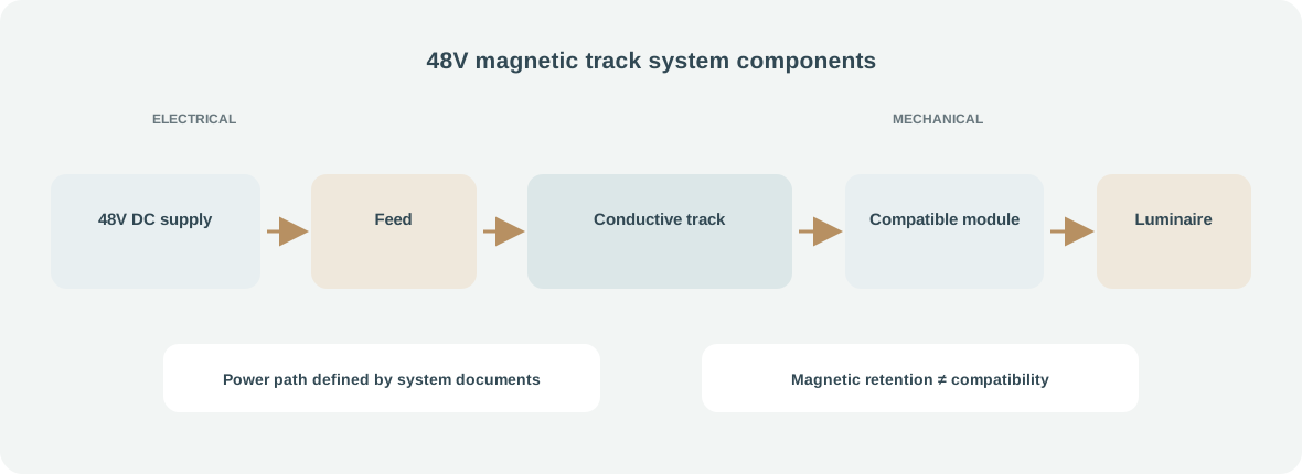
A typical system combines a 48V DC power supply, a track with conductors, a power-feed connector, the track sections and joints, and luminaires with matching adapters. Depending on the design, an LED driver may be inside each luminaire, inside its adapter, or elsewhere in the system. Some products use separate control conductors or a dedicated control interface. The system documentation, rather than the voltage label alone, defines the arrangement.
The key procurement task is to verify that track, feed, connectors, modules, driver and control form one documented system; 48V alone is insufficient.
For commercial projects, this system is one option within the broader commercial lighting range; confirm the exact track and module combination as a complete system.
Main Components of a Magnetic Track Lighting System
A track profile provides the physical channel and carries conductors. Profiles vary in width, depth, material, mounting detail and conductor layout. A magnetic luminaire module contains an optical assembly and an adapter that locates it on the rail. The adapter may combine magnetic retention with a latch, spring or other mechanical feature; do not assume magnetism alone is the safety retention mechanism.
Electrical contacts connect the module to the track conductors. Their spacing, number, shape and polarity are system-specific. A power supply produces the track output and a feed connector introduces it. Straight, corner or flexible joints continue the route; an end cap is not necessarily an electrical insulator.
Mounting accessories support recessed, surface-mounted or suspended installation. A control interface may be integrated into the supply, luminaire or a separate control device. Some systems have no data bus in the rail at all. The following component sketch is conceptual and does not represent a FANXING internal product drawing.
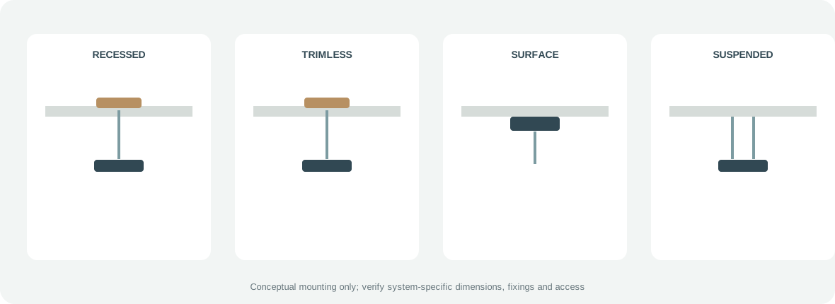
Recessed, Surface-Mounted and Suspended Tracks
Mounting method is a building coordination decision as much as a lighting choice. Check ceiling depth, framing, access to the supply, finish tolerances, installation sequence and future service access before specifying a profile.
| Installation | Building conditions to check | Access and maintenance | Often considered for |
|---|---|---|---|
| Recessed | Ceiling cavity, structural support, cut-out and driver access | Clean ceiling line; access may require a service opening or removable section | New ceilings and coordinated interior fit-outs |
| Trimless recessed | Precise plasterboard or plaster finish, edge detail and installation sequence | Visually minimal after finishing; repairs and alignment are less forgiving | Projects with a continuous, flush ceiling intent |
| Surface-mounted | Substrate strength, profile fixing method and visible profile depth | Track remains accessible; surface and fasteners stay visible | Existing ceilings, renovations or exposed construction |
| Suspended | Suspension points, ceiling height, load path, feed routing and movement control | Accessible from below, but suspension and wiring need inspection | Tall spaces, retail, hospitality and areas where the rail is a visible element |
These descriptions are planning prompts, not universal dimensions or fixing instructions. Different manufacturers use different sections, brackets and joining methods. Confirm the selected system’s installation sheet and the project’s structural requirements.
How Does the 48V Power Supply Work?
The installation supply is commonly AC mains. An AC/DC power supply converts that input to a 48V DC output, subject to its design and product rating. That output may feed track conductors directly. Each luminaire may then use an onboard DC/DC or LED driver to regulate the current through its LED source. Other architectures put more of the conversion in a central driver or use a different output method. Follow the exact system diagram.
Constant-voltage and constant-current supplies are not interchangeable. A constant-voltage supply regulates an output voltage, such as a rated 48V DC bus, while the connected loads draw current within the supply and distribution limits. A constant-current driver regulates current through a specified LED load over a defined output-voltage range. Connecting a load to the wrong type can cause failure, damage or unsafe operation. Use only the supply type and operating range specified for the track and modules.
Check the rated output voltage, continuous output current, rated power, permitted ambient temperature, thermal derating, overload protection and any required ventilation. Warm ceiling cavities can reduce continuous output. Losses, connectors and control electronics also affect capacity.
Input and output separation, earthing, insulation, enclosure and wiring are properties of the particular design. A 48V output does not by itself establish SELV, Class III, touch safety or compliance with a certification scheme. Those conclusions require the complete equipment, installation conditions and applicable assessment. IEC 60598-1:2024 sets general luminaire safety requirements and tests; the IEC publication summary describes its scope but is not a substitute for the applicable standard or product file.
How to Calculate Power Supply Capacity
For a nominal DC load, the basic relationships are:
P = V × I I = P / V
Illustrative Example
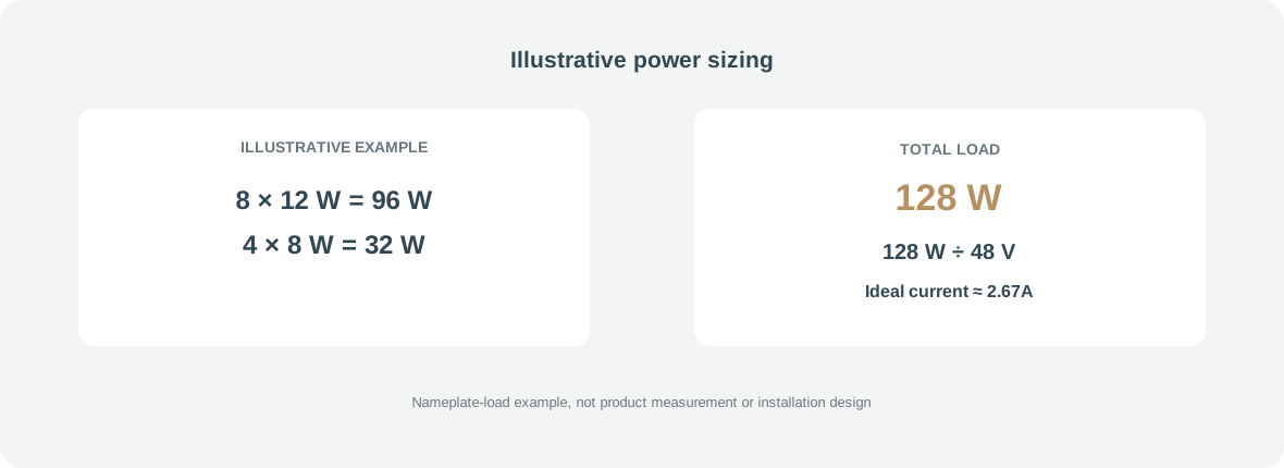
Assume, only for calculation practice, a layout with eight 12W spotlights and four 8W linear modules:
- Spotlights: 8 × 12W = 96W
- Linear modules: 4 × 8W = 32W
- Total nominal load: 96W + 32W = 128W
- Ideal current at 48V DC: 128W / 48V ≈ 2.67A
This is an idealized nameplate estimate, not a FANXING measurement, product specification, supply selection or complete electrical design.
Before choosing equipment, verify the supply’s continuous output rating at the actual ambient temperature, the track and connector current ratings, voltage drop, driver input requirements, startup behavior, dimmer or controller consumption, and the manufacturer’s rules for feed locations and load distribution. Some layouts need multiple feeds or zones. Use only the margin required by product documentation and project design; a generic percentage is no safety guarantee.
Keep LED module power and power-supply output capacity conceptually separate. If module data describes input power at the track, use that input figure consistently. If it gives LED-source power before driver losses, include the driver’s specified input demand and efficiency. Do not mix source watts, luminaire watts and track-side watts in one total without checking what each number means.
Voltage Drop in Long Magnetic Track Systems
Voltage drop is the reduction in voltage along a current-carrying path. For a simple lumped path, the basic circuit relation is:
Vdrop = I × R
Here, R is the resistance of the complete path being considered. Resistance depends on conductor material, length, cross-section, temperature and contact condition. In a two-conductor circuit, the outgoing and return paths both matter. Track joints, feeds and adapter contacts can add resistance.
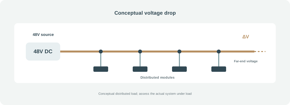
A long DC rail can have uneven voltage because modules draw current at different points along the track. The current in the first section may be the sum of downstream loads, while later sections carry less. Therefore, multiplying total luminaire current by the resistance of one arbitrary piece does not accurately model every distributed track. Multiple feed positions, separate branches, conductor geometry and contact resistance can change the result.
A deliberately simplified teaching example: if a particular complete supply-to-load path had a measured resistance of 0.20Ω and 2A flowed through that entire path, the estimated drop would be 2A × 0.20Ω = 0.40V. At an ideal 48.0V source that path would see about 47.6V, before considering other connections. These assumed values are not specifications for a FANXING rail and should not be used to approve a real installation.
For projects, obtain conductor data and permitted feeds from the supplier. Measure or calculate far-end voltage under expected load and compare it with the module input range. If needed, discuss another feed or shorter sections with the supplier; confirm polarity and protection first.
Are Magnetic Track Systems from Different Brands Compatible?
Not necessarily. Matching the 48V rating does not guarantee compatibility. Two systems can share a nominal voltage while differing mechanically and electrically.
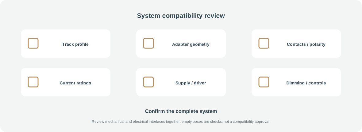
Compare the track profile dimensions and adapter geometry; magnetic retention and any mechanical latch; contact number, spacing and polarity; conductor arrangement; current rating; feed connector; and the luminaires’ driver requirements. Then check dimming protocol, extra control conductors, installation method and the safety approvals applicable to the complete combination. A module may appear to fit while failing to make reliable contact, having the wrong polarity, exceeding a rating or lacking a required control path.
One useful example is iGuzzini’s product page for model 251C: the manufacturer identifies a 48V DC Superrail track module with a track adapter, DALI control and a separately ordered track power supply. Those details describe that specific product and system, not a universal interface or a FANXING product. See the iGuzzini 251C technical page for its stated configuration.
For purchasing, request written compatibility confirmation covering the exact track, feed, connectors, modules and driver. Treat an adapter that merely fits as unverified until electrical operation and installation requirements are confirmed.
Dimming and Smart Controls: DALI, 0–10V and Wireless
48V describes an electrical supply level; it does not name a dimming protocol. A luminaire may be fixed-output, dimmable by a driver input, controlled through an onboard receiver, or part of a system with dedicated control conductors. The control path must be identified separately from the power path.
DALI is a digital lighting-control protocol based on the IEC 62386 series. A DALI system includes compatible control gear and control devices; a bus power supply powers DALI communication, not the 48V LED track load. The DALI Alliance introduction explains the protocol, while its systems and components overview distinguishes LED control gear, application controllers, input devices and bus supplies. Do not connect a DALI bus as though it were the track’s 48V output.
A 0–10V interface is an analog control input on compatible equipment. It may require separate control conductors and a compatible driver. Wireless control depends on the receiver, radio system, gateway and commissioning method specified for that product. “Dimmable” alone does not identify which of these methods is supported. Obtain the driver model, control wiring diagram and tested control-device list before procurement.
LED Module Types and Optical Selection
Magnetic rails may accept spotlights, linear modules, grille or louvre modules, adjustable heads and, where offered, decorative forms. Availability and optical options vary by system. For commercial lighting, begin with the space task and required distribution rather than assuming that a single module type covers every application.
Use verified product data to compare distribution, CCT, CRI, efficacy, glare control, adjustment and maintenance access. For calculations, request photometry for the exact optic and configuration. A model name or beam angle cannot establish illuminance or uniformity; FANXING specifications must come from current product documents.
Installation and Commissioning Checklist
Use this checklist to coordinate design and handover. It is not a terminal-by-terminal wiring instruction.
- Confirm one documented track family and its required accessories.
- Verify the AC input conditions and rated 48V DC output on the selected supply.
- Confirm driver and luminaire compatibility for the intended modules.
- Check the actual recessed, trimless, surface or suspended mounting method.
- Verify total load and current against the supply, track, joints and feed ratings.
- Confirm contact polarity and conductor assignment from the system documentation.
- Inspect every section connector and power feed for the specified seating and retention.
- Assess voltage drop and the farthest-point input under expected load.
- Confirm DALI, 0–10V, wireless or other control interface end to end.
- Verify isolation, enclosure and protection required by the design and local rules.
- Test representative modules and controls before ceilings are closed or handover is complete.
- Record the final parts list, supply configuration and maintenance instructions.
Mains input and fixed wiring should be installed and verified by a qualified electrical professional under local requirements. Do not infer wire colours, terminal positions, screw torque, maximum rail length or feed spacing when the selected product manual does not state them.
Common Problems and Troubleshooting
| Problem | Possible causes | What to check |
|---|---|---|
| Fixtures do not turn on | No AC input, supply protection active, wrong output type, reversed or open track contacts | Confirm supply status and rated output; have a qualified person verify the documented input and output path |
| Intermittent contact | Module not fully seated, worn or contaminated contact, loose joint, mechanical retention issue | Isolate power as required; inspect adapter engagement and connectors against the manual |
| Flickering | Incompatible dimmer, driver instability, loose contact, control wiring issue or overloaded supply | Test at full output; isolate the control path from the power path and verify the driver and total load |
| Uneven brightness | Voltage variation, different module configurations, optics or dimming settings | Compare module data and dimming values; measure the far end under load and review feed locations |
| Module cannot be installed | Different profile, adapter, polarity key or mechanical latch | Stop rather than force it; verify the exact track/adapter family |
| Dimming does not work | DALI/0–10V mismatch, missing bus or controller, unsupported receiver, incorrect commissioning | Identify the control method and check every connected device and bus supply |
| Power supply overloads | Load exceeds continuous rating, poor thermal conditions, startup demand or wrong supply | Recalculate from actual input ratings and ambient derating; check manufacturer load and protection guidance |
| Excessive heat | Inadequate ventilation, overloaded supply, unsuitable enclosure or poor connection | De-energize if unsafe; check installation clearances, ratings and connection condition with a qualified professional |
Symptoms can have several causes; check mechanical fit, power, driver and control separately.
Safety Standards and Compliance
Standards apply according to the actual equipment and installation. IEC 60598-1:2024 covers general luminaire safety requirements and tests. IEC 61347-2-13:2024 addresses safety requirements for electronic controlgear for LED light sources. These references help identify the relevant product-documentation discussion; naming a standard here is not a claim that a particular FANXING product has been tested or certified to it.
The public IEC 60570 scope describes ordinary indoor electrical-supply track systems with two or more poles and provision for earthing (Class I), within its stated voltage, frequency and current limits. It should not be presented as an automatic blanket standard for every 48V magnetic track or Class III design. Confirm the current applicable edition, national adoption, system classification and product evidence for the intended installation.
A 48V label alone does not establish SELV, Class III, touch safety or exemption from electrical-safety requirements. Confirm the complete power supply, isolation, wiring, enclosure, track, connectors and luminaires against the applicable regulations in the destination market. Ask for genuine certificates and reports for the exact product family; do not infer CE, ENEC, UL, ETL or DALI-2 status from a voltage or control label.
What Information Should Buyers Provide to a Manufacturer?
A manufacturer can check a proposed configuration more efficiently when the request separates known requirements from choices still open. Send the following where available:
- Recessed, trimless, surface-mounted or suspended installation type.
- Track layout, total lengths, corners, joints and proposed feed positions.
- Required track profile and any existing system whose compatibility is requested.
- Quantities and types of spot, linear, grille or adjustable modules.
- Module input power, supply voltage and driver configuration.
- Dimming or control requirements, including DALI, 0–10V or wireless details.
- CCT, CRI, beam distribution and glare-control targets supported by project documents.
- Reflected ceiling plan, elevations, section details and control drawings.
- Applicable destination-market certificates or compliance documents.
- Expected quantities, sample needs and project timeline.
For system development, discuss the confirmed interface and the unresolved items with FANXING custom lighting and review the manufacturing process. Send the layout and requirements through the project inquiry form. A drawing review is a starting point, not an engineering approval until the exact product and installation data are confirmed.
Frequently Asked Questions
Are all 48V magnetic track lights compatible?
No. Confirm the track profile, adapter, contacts, polarity, current rating, driver and control method as a system. Matching voltage is not proof of fit or electrical compatibility.
How many lights can run on one 48V power supply?
There is no universal count. Add the input power of the selected modules, divide by the rated bus voltage for a first current estimate, then check continuous supply capacity, track and connector ratings, derating, voltage drop and feed arrangement.
Can I mix magnetic spotlights and linear modules?
Only if the track supplier documents both module families for the same track and power/control configuration. Similar-looking adapters may not use the same contacts or ratings.
Why do my 48V track lights flicker?
Possible causes include unstable or unsuitable supply, loose contacts, incompatible dimming equipment, control wiring or excessive load. Compare behavior at full output and use the product instructions to separate the power and control paths.
Do magnetic tracks support DALI?
Some system configurations may; the 48V rating does not imply DALI. Confirm that the specific track module or driver, control conductors, DALI bus supply and controller are compatible.
What causes voltage drop in long magnetic tracks?
Conductor resistance, the amount and location of load, track joints, feed contacts and supply-point layout can all contribute. Check the farthest loaded point and use the manufacturer’s specified feed topology; there is no generic maximum length for every rail.
Is a 48V magnetic track system automatically safe to touch?
No. Voltage alone does not determine the safety classification of the complete assembly. Verify the power supply, isolation, construction, installation and applicable local requirements.
Can magnetic track lights be installed after the ceiling is finished?
Surface-mounted or suspended systems may suit some finished ceilings, while recessed and trimless tracks usually require coordination with ceiling construction and finishing. Check the selected profile, structural support and access instructions before deciding.
Technical References
1. IEC — IEC 60598-1:2024, Luminaires: General requirements and tests. 2. IEC — IEC 61347-2-13:2024, Electronic controlgear for LED light sources. 3. IEC — IEC 60570, Electrical supply track systems for luminaires: consolidated scope. 4. DALI Alliance — Introducing DALI. 5. DALI Alliance — DALI-2 systems and components. 6. iGuzzini — 251C, a specific 48V DC Superrail DALI product example.
Discuss a 48V Magnetic Track Lighting Project
Share the track layout, installation type, module mix, supply and control requirements, drawings and destination market with FANXING LIGHTING through the project inquiry form. FANXING can review the stated requirements for a custom lighting or OEM/ODM discussion; system compatibility, compliance and final installation remain subject to confirmation against the selected product documentation and project design.